Rationale
Touchdesigner already has a nice set of basic operators for building geometry
like the SphereSOP or the
GridSOP.
However there might be use cases where you need to work with custom and
adjustable geometry, e.g. I recently needed to have wall mesh
that exactly matches an LED-wall in order to have the output on
the display controllers match seamless with the LED-ceiling. Experimenting with the ScriptSOP and geometric formulas lead to a series of generative
organic structures afterwards.
Herinafter, the basic usage of Touchdesigners Python API in ScriptSOPs
is described. We'll start by building a simple quad and will move to more
complex structure like a sphere and a so-called supershape. I've put up a
repository with all the examples below at
github.com/guidoschmidt/Touchdesigner.GenerativeMeshes.
Quad
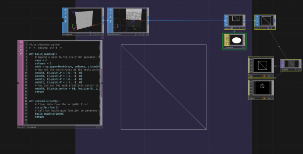
At the beginning, to understand the basic API, we'll build a simple quad:
- Put a ScriptSOP onto the Touchdesigner canvas
- We'll now write a simple function that will draw a quad on the XY-plane
reaching from
[-1, -1] to [+1, +1]
on the xy-plane
- In the python script of the
ScriptSOP, we make use of the
appendMesh()
function:
def build_quad(op):
    # Append a mesh to the ScriptSOP operator, that contains 2 rows and 2 colums
    rows = 2
    columns = 2
    mesh = op.appendMesh(rows, columns, closedU=False, closedV=False, addPoints=True)
    # Now set the coordinates of the meshs points
    mesh[0, 0].point.P = [+1, +1, 0]
    mesh[0, 1].point.P = [-1, +1, 0]
    mesh[1, 0].point.P = [+1, -1, 0]
    mesh[1, 1].point.P = [-1, -1, 0]
    # You can set the mesh primitives center to a 3d position
    mesh[0, 0].prim.center = tdu.Position(0, 1, 0)
    return


def onCook(scriptOp):
    # Clear data from the scriptOp first
    scriptOp.clear()
    # Call our build_quad function to generate the quad mesh
    build_quad(scriptOp)
    return
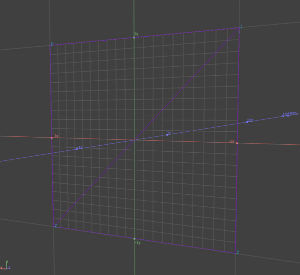
Notice that TDs appendMesh function is defined from a grid of rows and
columns. Using the OpenGL topology wireframe options on any material reveals the underling triangle structure.
Ribbon
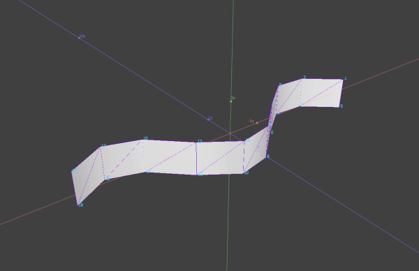
As a next step we extend the quad in one direction to generate a row of quads forming a ribbon like structure. To do so, we write a function that accepts a parameter rows. This parameter defines
the count of rows in X direction. Here we also change the z value of the mesh
vertices by using row index as parameter for the sine function. This bends the ribbon into a repeating wave shape.
def build_ribbon(op, rows):
    columns = 2
    mesh = op.appendMesh(rows, columns, closedU=False, closedV=False, addPoints=True)
    # rows comes in as a parameter and defines how many rows the ribbon should
    # have. We need to iterate over a range of indices from 0 to rows:
    for row in range(mesh.numRows):
        # To get a wavy look the z coordinate is calculated
        # using the sinus function
        mesh[row, 0].point.P = [row, 0, math.sin(row)]
        mesh[row, 1].point.P = [row, 1, math.sin(row)]
    # The mesh primitive is placed onto position [0, -1, 0] in 3D space:
    mesh[0, 0].prim.center = tdu.Position(0, -1, 0)
    return


def onCook(scriptOp):
    # Clear data from the scriptOp first
    scriptOp.clear()
    build_ribbon(scriptOp, 10)
    return
Grid
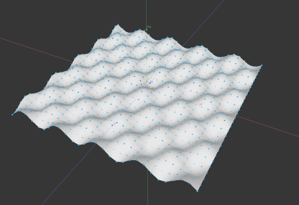
Now let's extend the ribbon again and write a function to generate a grid. In
the following example I did modulate the y coordinate using y = math.sin(row + 1.5) * math.cos(col) in order to create a more interesting landscape-alike
shape (if you like you can try to use a noise function to modulate the y
coordinate):
def build_grid(op, sx, sy):
    mesh = op.appendMesh(sx, sy, closedU=False, closedV=False, addPoints=True)
    for row in range(mesh.numRows):
        for col in range(mesh.numCols):
            y = math.sin(row) * math.cos(col)
            mesh[row, col].point.P = [row, y, col]
    # Instead of writing tdu.Position(0, 0, 1) you can also
    # use pythons list syntax:
    mesh[0, 0].prim.center = [0, 2, 0]
    return


def onCook(scriptOp):
    scriptOp.clear()
    build_grid(scriptOp, 30, 30)
    return
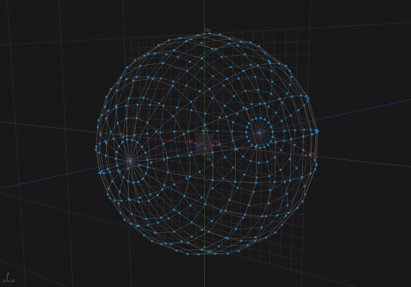
Globe
To script a globe mesh, we will make use of the spherical
coordinates. In order
to avoid connections between the poles on the sphere, we only iterate up to maximum
row count minus 1. To apply a texture on the mesh, we could additionally add
texture coordinates as a mesh attribute or use a TextureSOP afterwards.
def build_globe(op, sx, sy):
    mesh = op.appendMesh(sx, sy, closedU=True, closedV=False, addPoints=True)
    radius = 10
    # In order to prevent connection between north and south pole
    # of the globe mesh, we need to iterate only up to numRows - 1
    row_count = mesh.numRows - 1
    col_count = mesh.numCols
    for row in range(mesh.numRows):
        lat = (row / row_count) * math.pi - (math.pi / 2)
        for col in range(mesh.numCols):
            lng = (col / col_count) * math.pi * 2 - math.pi
            x = radius * math.cos(lng) * math.cos(lat)
            y = radius * math.sin(lng) * math.cos(lat)
            z = radius * math.sin(lat)
            mesh[row, col].point.P = [x, y, z]
    mesh[0, 0].prim.center = [0, 0, 0]
    return


def onCook(scriptOp):
    scriptOp.clear()
    build_globe(scriptOp, 30, 30)
    return
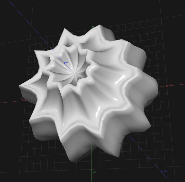
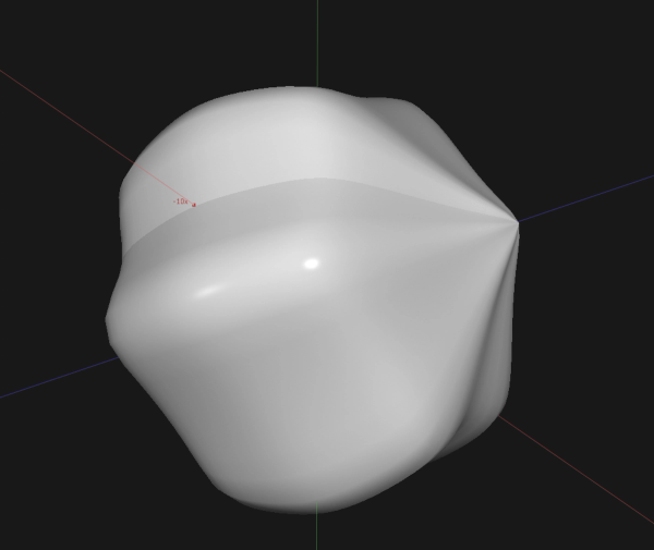
Supershape
If you have seen my recent posts
from my series Liveforms of Generative Geometry,
the following section describes the basic technique behind these generative
meshes. I've appled Paul Bourkes supershape
formulas to the sphere coordinates
we scripted in the preceding example. The supershape formulas lives in
its own function to separate the mesh generation itself from the supershape magic:
def supershape(theta, m, n1, n2, n3):
    a = 1
    b = 1
    t1 = abs((1 / a) * math.cos(m * theta / 4))
    t1 = math.pow(t1, n2)
    t2 = abs((1 / b) * math.sin(m * theta / 4))
    t2 = math.pow(t2, n3)
    t3 = t1 + t2
    r = math.pow(t3, -1 / n1)
    return r


def build_supershape(op, sx, sy):
    m = 10.0
    n1 = 1.5
    n2 = 1.3
    n3 = 2.0
    lng_rng = math.pi / 2
    lat_rng = math.pi * 2
    mesh = op.appendMesh(sx, sy, closedU=False, closedV=False, addPoints=True)
    radius = 10
    row_count = mesh.numRows - 1
    col_count = mesh.numCols - 1
    for row in range(mesh.numRows):
        lat = (row / row_count) * lng_rng
        r2 = supershape(lat, m, n1, n2, n3)
        for col in range(mesh.numCols):
            lng = (col / col_count) * lat_rng - (lat_rng / 2)
            r1 = supershape(lng, m, n1, n2, n3)
            x = radius * r1 * math.cos(lng) * math.cos(lat)
            y = radius * r1 * math.sin(lng) * math.cos(lat)
            z = radius * r2 * math.sin(lat)
            mesh[row, col].point.P = [x, y, z]
    mesh[0, 0].prim.center = [0, 0, 0]
    return
Debugging
Scripts that generate geometry and meshes are hard to debug and it's not always
straight forward to understand what is going on. In order to better understand
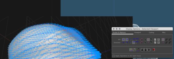
the topology of a scripted mesh, try to make extensive use of Display Options. Right-clicking into any SOP operator, select Display Options. Display of vertex order, normals or uv coordinates can help to get a
better understanding of the topology and help to find bugs or errors in the
implementation.
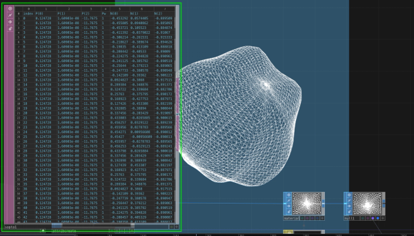
You can also make use of a SOP to DAT operator to get a list of all the geometryinformation from a SOP, which is super helpful to check vertices, primitives
and attributes of a mesh.
References
